 |
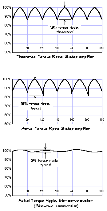
Notice, that
the torque ripple for a perfectly 6-step commutated motor is 13%. However,
due to several factors-Hall-sensor-to-Hall-sensor misalignment (Hall-device-to-motor
package, motor package to Hall circuit board), hysteresis in the Hall-sensors
(required to quell oscillation when the motor lands on commutation points)
and localized magnetic variations in the magnetic field of the rotor near
the Hall-sensor array-the actual torque variation is typically 17% to
20%. This torque ripple (inaccuracy) causes vibration, noise, mechanical
wear, and greatly reduced servo performance.
 A secondary
effect of 6-step misalignment, is a reduction in continuous torque capability
due to useless heating of the motor windings. The heating of the motor
coils is proportional to the square of the current, independent of whether
it produces torque or not. So the portion of current in the windings that
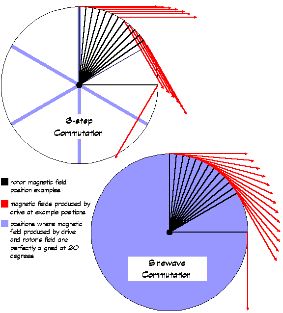
produces a magnetic field that is not ninety degrees to the rotor's magnetic
field, produces harmful heat. This heating, along with the poor utilization
of the copper in the motor (caused by only using two phases of the motor
instead of three), significantly reduces the continuous torque capability
of the motor. This means you'll need to use a larger, more expensive motor
(which often also means using larger and more expensive mechanical components,
such as gearboxes.) Typical experimental results show that a motor will
have 15% more continuous torque capability when driven by the SST servo
drive rather than a 6-step servo amplifier. A secondary
effect of 6-step misalignment, is a reduction in continuous torque capability
due to useless heating of the motor windings. The heating of the motor
coils is proportional to the square of the current, independent of whether
it produces torque or not. So the portion of current in the windings that
produces a magnetic field that is not ninety degrees to the rotor's magnetic
field, produces harmful heat. This heating, along with the poor utilization
of the copper in the motor (caused by only using two phases of the motor
instead of three), significantly reduces the continuous torque capability
of the motor. This means you'll need to use a larger, more expensive motor
(which often also means using larger and more expensive mechanical components,
such as gearboxes.) Typical experimental results show that a motor will
have 15% more continuous torque capability when driven by the SST servo
drive rather than a 6-step servo amplifier.
 The
above analysis of the debilitating effects of 6-step commutation leaves
out one important, yet seldom mentioned, effect. What happens when a phase
that has current flowing through it, is disconnected (unhooked and left
"open-circuit")? Ideally, the current in this phase would immediately
drop to zero. Unfortunately, for systems employing 6-step amplifiers,
this is physically impossible because of the inductance in the coil. As
we know, the laws of physics won't allow the current in a coil to drop
to zero immediately. It will continue to flow for approximately several
times the inductive time constant of the motor windings. (This happens
without arcing because the winding is not truly left open circuit-it "flies"
into a catch diode in the output stage.) This effect leads to sharp torque
pulsations at the commutation points, which the current loop can't fully
correct. As you can imagine, this is hardly what you want inside your
servo loop. The ripple and pulsing are a major source of disturbance,
which typically leads to de-tuning the servo system and affects settling
time, tracking, acoustical noise and obviously, smoothness. In addition,
for additional reasons that are beyond the scope of this discussion, 6-step
drives also have very poor dynamic response, further reducing the fidelity
of control at speed. The
above analysis of the debilitating effects of 6-step commutation leaves
out one important, yet seldom mentioned, effect. What happens when a phase
that has current flowing through it, is disconnected (unhooked and left
"open-circuit")? Ideally, the current in this phase would immediately
drop to zero. Unfortunately, for systems employing 6-step amplifiers,
this is physically impossible because of the inductance in the coil. As
we know, the laws of physics won't allow the current in a coil to drop
to zero immediately. It will continue to flow for approximately several
times the inductive time constant of the motor windings. (This happens
without arcing because the winding is not truly left open circuit-it "flies"
into a catch diode in the output stage.) This effect leads to sharp torque
pulsations at the commutation points, which the current loop can't fully
correct. As you can imagine, this is hardly what you want inside your
servo loop. The ripple and pulsing are a major source of disturbance,
which typically leads to de-tuning the servo system and affects settling
time, tracking, acoustical noise and obviously, smoothness. In addition,
for additional reasons that are beyond the scope of this discussion, 6-step
drives also have very poor dynamic response, further reducing the fidelity
of control at speed.
|


