 |
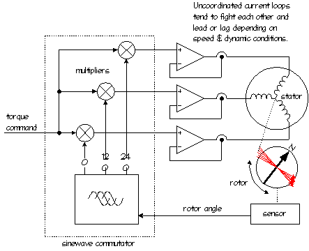
The first thing youíll notice is that the current loops in a sinewave
amplifier operate in an uncoordinated fashion. However, the phases
themselves are connected together, so the currents are dependent
upon each other.
 Letís
explore a simple analogy that describes the dilemma this causes: Imagine
you are in a house with two bathrooms. You and your spouse are both taking
showers at the same time (in separate bathrooms) and you decide you want
the water a little hotter. So you, like the independent current loop,
open up your hot water valve a little more. You get hotter water, but
because you are "connected" through the hot water pressure, your spouseís
water cools down. So your spouse adjusts to maintain the desired water
temperature. This goes on for a few moments with both of you adjusting
your water valves until you find an equilibrium that suits both of you.
Now imagine what would happen if you were trying to constantly change
the water temperature along some arbitrary profile, like the sine angles
trying to follow the arbitrary position of the rotor? It would be nearly
impossible for you and your spouse to do this accurately without communicating
and coordinating. Add a little noise or imbalance (someone washing the
dishes or flushing a toilet) and it gets even harder. So because the current
sensors have some noise, and the rotorís back-EMF is not a true sinewave,
and the amplifier may run out of voltage headroom, etc., a sinewave amplifier
will naturally induce torque fluctuations as the independent current loops
seek an equilibrium. Letís
explore a simple analogy that describes the dilemma this causes: Imagine
you are in a house with two bathrooms. You and your spouse are both taking
showers at the same time (in separate bathrooms) and you decide you want
the water a little hotter. So you, like the independent current loop,
open up your hot water valve a little more. You get hotter water, but
because you are "connected" through the hot water pressure, your spouseís
water cools down. So your spouse adjusts to maintain the desired water
temperature. This goes on for a few moments with both of you adjusting
your water valves until you find an equilibrium that suits both of you.
Now imagine what would happen if you were trying to constantly change
the water temperature along some arbitrary profile, like the sine angles
trying to follow the arbitrary position of the rotor? It would be nearly
impossible for you and your spouse to do this accurately without communicating
and coordinating. Add a little noise or imbalance (someone washing the
dishes or flushing a toilet) and it gets even harder. So because the current
sensors have some noise, and the rotorís back-EMF is not a true sinewave,
and the amplifier may run out of voltage headroom, etc., a sinewave amplifier
will naturally induce torque fluctuations as the independent current loops
seek an equilibrium.
 The
second failing of the simple sinewave-commutated amplifier is that the
current loop response delay forces the currents to lead or lag (depending
upon where within the four quadrants of operation the motor is operatingómotoring,
braking , accelerating, etc.). As the speed becomes higher, the rate of
change of the sinewave demand gets faster and the phase error becomes
more significant. This lead or lag in time directly affects the angle
of the magnetic vector produced in the motor, moving it off the ninety
degree mark, causing torque to be reduced (and inaccurate relative to
the position/velocity compensatorís command) and heating increased. The
second failing of the simple sinewave-commutated amplifier is that the
current loop response delay forces the currents to lead or lag (depending
upon where within the four quadrants of operation the motor is operatingómotoring,
braking , accelerating, etc.). As the speed becomes higher, the rate of
change of the sinewave demand gets faster and the phase error becomes
more significant. This lead or lag in time directly affects the angle
of the magnetic vector produced in the motor, moving it off the ninety
degree mark, causing torque to be reduced (and inaccurate relative to
the position/velocity compensatorís command) and heating increased.
 The
third problem is caused by limited voltage headroom as the motor approaches
rated speed. This is a little harder to explain, but suffice it to say
that without an active measurement and control of the magnetic vector,
these amplifiers run out of headroom earlier as speed is increased, drastically
affecting their Torque Response Time. (If youíre an electrical engineer,
this is analogous to having reduced large signal bandwidth.) So, just
when you need a rapid reversal in torque, say at the peak speed of a triangle
move, your sinewave amplifier will delay its response, affecting your
tracking accuracy and settling time. This reduced "large signal response"
also typically limits your ability to turn up the position/velocity compensator
gains, which further limits your stiffness, tracking accuracy and settling
time. The
third problem is caused by limited voltage headroom as the motor approaches
rated speed. This is a little harder to explain, but suffice it to say
that without an active measurement and control of the magnetic vector,
these amplifiers run out of headroom earlier as speed is increased, drastically
affecting their Torque Response Time. (If youíre an electrical engineer,
this is analogous to having reduced large signal bandwidth.) So, just
when you need a rapid reversal in torque, say at the peak speed of a triangle
move, your sinewave amplifier will delay its response, affecting your
tracking accuracy and settling time. This reduced "large signal response"
also typically limits your ability to turn up the position/velocity compensator
gains, which further limits your stiffness, tracking accuracy and settling
time.
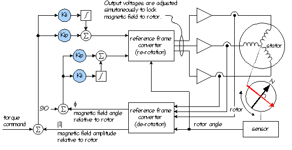
So what is Closed-Loop
Vector Torque Control?
In contrast
to the simple sinewave amplifier that uses the sinewave references as
commands to uncoordinated current loops, the SST servo driveís closed-loop
vector torque controller uses the sinewave references in mathematical
transforms to "de-rotate" the amplitude and angle of the electromagnetic
vector from the measured currents. Then, after the torque loop calculates
the voltage amplitude and angle, another transform "re-rotates" these
into the three simultaneous voltages provided to the motor. See the diagram
below. contrast
to the simple sinewave amplifier that uses the sinewave references as
commands to uncoordinated current loops, the SST servo driveís closed-loop
vector torque controller uses the sinewave references in mathematical
transforms to "de-rotate" the amplitude and angle of the electromagnetic
vector from the measured currents. Then, after the torque loop calculates
the voltage amplitude and angle, another transform "re-rotates" these
into the three simultaneous voltages provided to the motor. See the diagram
below.
|


