Learn how the SSt all digital servo system with vector torque control compares with other more traditional motion control alternatives.
Investigating Servo Architectures- Pros and Cons


The following discussion, to the best of our knowledge is the only public description of the subtle, yet substantial differences between servo control boards, various torque amplifiers, and the various architectures used in digital servo drives on the market today.
Why have we gone to the effort of explaining these subtleties? Simply put, because the difference between SSt servo drives and competing solutions is so compelling that we thought you would want to know how WorldServo™ is able to offer you this superior performance (and at such low cost!).
Briefly (much more about this later), the SST servo uses a dedicated DSP microprocessor on every axis, with proprietary algorithms that synchronously controls position, velocity and vector torque (rather than motor current). For many reasons, this superior architecture allows state-of-the-art performance along with ease-of-use and low cost. We'll demonstrate how the SSt Servo Systems provide you with:

  1. High Performance—It's easy to make claims about high performance, and we're sure you've heard them from our competitors. However, most performance specifications offered by servo component vendors (sample time, #DAC bits, PWM rate, etc.) have surprisingly little or no effect on the quality of the motion. What really differentiates servo systems is how quickly and how intelligently they respond to commands and disturbances—real-world, overall system bandwidth. We'll explain how the SST servo system's all-digital architecture, with a dedicated DSP processor per axis, provides you with not only a fundamentally superior control platform, but also supports several proprietary features that give you more usable system bandwidth. This means tighter, faster, smoother axis operation than is possible with competing solutions.

  2. Ease-of-Use—actually, not simply ease-of-use, but rather, "Ease-of-Performance™"—high-performance that is easily achievable. The superior performance, made possible by the SST servo drive's architecture, is not locked away, accessible only to control experts. With the powerful combination of the SST's automatic adaptive tuning, the QuickSet™ configuration/tuning/debug software, and the immediate feedback of the Real-time Monitor Port, you can obtain state-of-the-art performance quickly and repeatedly without having any specialized servo knowledge.
     Several proprietary features inside the SST servo drives also reduce your development efforts and speed the time-to-market of your machine. To find out more about Ease-of-Performance™ take a look at the following benefits when you are done reading this page:

Simplified Control Software Development

Easy System Debug/Configuration

Easy Electrical Integration

Enhanced Design Flexibility

Easy, Repeatable Setup during machine manufacture

Most of these benefits are directly related to proprietary features that can only be implemented using the SST architecture.

Comparing Architectures


Below under "Experimental Results" you will see actual data that confirms the superior performance of the SST servo drives when compared against systems based upon "centralized" controller boards or other digital drives. Before you look at these experimental results we would like to give you some insight as to why these improved results are possible when you use SST servo drives. To do this we need to examine the architectural differences in servo systems.


Servos using Traditional (centralized) Controller Boards
First, let's take a look at how older servo systems, based on centralized control boards are constructed. Examples of these centralized systems include the PMAC™ from Delta Tau Data Systems, the DMC™ series from Galil, Inc. and the DSP-PC from Motion Engineering, Inc. (MEI).
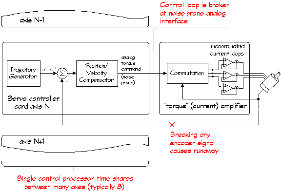
In these systems, a controller board is placed inside a host CPU and analog command signals and feedback signals are routed from all the drives and motors and bundled together to the controller board. A solitary processor is used to control many axes (usually 4 or 8), which time-shares its processing power between all the axes under control. The following block diagram illustrates how these systems work:

Traditional "High-performance" Servo Architecture. Notice that there is no torque loop! Torque is controlled open-loop. Only the individual currents are servo controlled (see text for why this causes problems).


You should notice several things about this block diagram

  1. The torque control is "open loop", i.e. there is no direct feedback enforcing that the torque being requested is actually obtained. In other words, at no point in this system is the torque actually measured and corrected. In fact, because the control of the currents in each motor phase is uncoordinated and because the currents are likely to lag or lead with respect to the rotor (or forcer in a linear motor), it is a near certainty that the torque will not be what was requested by the controller.
The actual torque in these systems is affected substantially by:
   a) the rate of change of torque demand,
   b) the speed of the motor,
   c) the angle of the rotor and
   d) the "quadrant" of operation (braking or accelerating).
What this means essentially, is that no matter how accurately the Position/Velocity compensator calculates the required torque (or force), it is unlikely to get it. As we will see, it is most likely that the Position/Velocity compensator won't get the requested torque just when it really needs it the most.

  2. These systems are broken (i.e., have an interface) at a critical point inside the control loop. This analog interface is typically run through cables in the presence of noise (the amplifier's PWM output, AC "hum", EFT pulses, etc.). The decreased resolution and noise-prone nature of this interface introduces disturbances within the main servo control loop, which increase servo hunting (jitter).

  3. The Position/Velocity compensator runs asynchronously to the current amplifier.
Even a completely analog amplifier has a natural "sample rate" at the PWM switching rate (typically, with an additional delay of another PWM cycle). Processor-based sinewave amplifiers have sample rates much slower than the PWM rate of analog amps (typically 0.5 milliseconds). [Linear class amplifiers, i.e., high power op-amps, are not considered here because their high cost, size, heat and low power rating makes the impractical for all but the lightest applications.]
The asynchronous nature of the two rates—the Position/Velocity compensator's sample rate and the amplifier's sample rate—introduces an additional, variable "phase delay" in the torque response. The worst-case delay is a minimum of the sum of the two sample periods. This additional delay in response degrades tracking accuracy and lengthens settling time.

  4. Finally, a critical failure will occur when the encoder signals are interrupted due to intermittent connectors, failure of cable due to flexing, actual encoder failure, etc. In these instances, the servo will run away (uncontrollably accelerate in one direction) typically causing machine damage and/or even bodily harm.


WorldServo SSt:
Total-Digital Servo with Vector Torque Control (VTC)
This architecture is a noticeable refinement over the more common Digital Sinewave Positioning Drive discussed below. Here, a high speed DSP control processor is used to control all of the feedback loops: position, velocity and actual torque. Torque is actively measured and controlled, and the losses in the motor are actively minimized. The operation is truly, totally digital: The motor currents are converted directly into digital format for the DSP, and the output to the motor are digital PWM pulse streams—no analog processing is used whatsoever. The SST servo drive, introduced in 1994, was the first commercially available unit to employ this architecture for permanent magnet brushless motors, and to our knowledge, is the only drive of its type on the market today (although there are a number of drives available that superficially appear to employ the same architecture.).
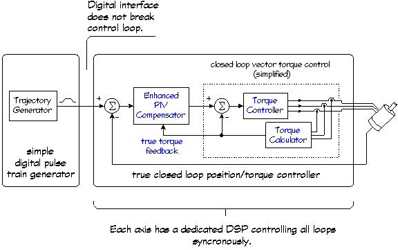
     The following block diagram highlights the structure of this Totally-Digital Servo with VTC architecture:

Totally-Digital Servo with VTC Control Architecture


You should notice several things about this block diagram.

  1. The vector torque controller actively measures and controls the actual torque (force) to the level that is requested by the Position/Velocity compensator. This is done by measuring all of the motor currents simultaneously and calculating both the vector amplitude and the vector angle of the resultant magnetic field (hence the term vector torque control) and locking this magnetic field to the rotor's position to produce the exact amount of torque requested. In addition to being accurate, this technique also reduces the torque response delay to a constant level, independent of the rate of change of torque demand, motor speed, shaft angle, or "quadrant" of operation. What this means is that the Position/Velocity compensator does not have to be "de-tuned" to accommodate the variable delay and variable amplitude response of an open loop "torque" amp. This leads to superior smoothness, enhanced disturbance rejection and short settling times.
     (After you read this section see the Closed-Loop Vector Torque Control feature for a good description of how this works.)

  2. There is no analog noise inserted within any of the control loops. The compensator/torque-controller interface is all-digital and free of any analog noise contribution or decreased resolution. The interface to the servo system is instead placed outside of the control loops at the trajectory command level. This digital interface is a pulse stream which is easily and inexpensively produced by a stepper motor indexer, or a couple of output bits on an embedded CPU, or a PC's parallel port, or with a PLC's timer/pulser output.
     (In fact, the SST servo drive's RAS feature greatly aids in the use of simple schemes for generating the trajectory pulse streams, and automatically converts simple, linear velocity profiles into smooth, jerk limited profiles. After you read this page see the Zero-cost controller capability feature for more detail on this).

  3. Inside a Totally-Digital Servo with VTC, the Position/Velocity compensator is completely synchronized with the vector torque control. There is no accumulation of sample time delays and the Total Servo Phase Delay (TSPD) can be as short as the raw time it takes to do the control calculations. In fact, the SST servo drive's TSPD (the elapsed time from when the encoder feedback and currents are read until the PWM outputs to the motor are modulated) is only 50 microseconds! TSPD has much greater effect on servo performance than the often-cited controller sample time. The SST servo drive is without peer in regard to this TSPD specification. (After you read this page see the Lowest TSPD on the market feature for more detail on this).

  4. Servo runaway due to lost or faulty encoder signals can not occur. Because the rotation of the magnetic vector is tightly linked to the encoder signals, loss of either encoder phase signal will stop the servo dead. These systems are therefore far more fail-safe than a traditional servo system even when used with TTL (inexpensive) encoders (where electrical loss of the encoder signal is undetectable).

  5. Control Synergy—The dedicated DSP processor within the SST servo drive knows, at all times: the state of the Position/Velocity compensator, the motor's magnetic field, the output voltages of the amplifier, the limit switch inputs, the RMS current in the motor, and a number of other variables. The SST's proprietary control algorithms have been specifically designed to make good use of all this information. The result has been superior performance in not only standard benchmarks (bandwidth, settling time, tracking accuracy), but also in subjective benchmarks such as quiet jitter-free operation, virtual elimination of overshoot, reduction of torque "chatter", and more. In addition, the DSP's knowledge of the entire state of the system has enabled WorldServo to produce several unique features. Thousands of hours of computer simulation and experimentation yielded, among other advantages, optimized operation of: Adaptive Inertia Matching Technology (IMT), Hard-stop homing, fuzzy MoveDone signal false trigger suppression, and automatic current sensor calibration. (To find out more about these features and their associated benefits go to the Features/Benefits page.).


Servos using Traditional Controller Boards with Sinewave Commutation

Before we leave this discussion, we should touch on two final system architectures that are becoming more commonplace. Both of these architectures attempt to reap the smoothness benefits of sinewave commutation, but they fall short of the improvements of closed-loop vector torque control.
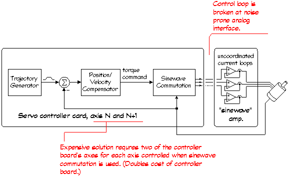
The first type of these hybrid systems, now being offered by many of the servo controller board vendors, is referred to as "onboard sinewave commutation" or "direct support of sinewave amplifiers". The following block diagram illustrates how these systems work:

Traditional Servo Architecture with a "Sinewave" amplifier


There are two advantages to this buttressed system: 1) torque ripple due to the abrupt commutation found in most brushless servo amplifiers (i.e., 6-step commutated) is eliminated and, 2) encoder signal loss will not cause runaway. However, all of the other disadvantages of the traditional servo architecture remain—lack of closed-loop torque control and thus torque inaccuracy under heavy demand, susceptibility to noise ingress in the analog commands, the variable delay caused by the asynchronous operation of the controller and amplifier, etc.
In addition, systems constructed with this architecture are expensive because two channels are required on the controller board to control each axis (e.g., a 4-axis board is required to control two axes) and the sinewave amplifiers are typically costly. In addition "lumpiness" due to sensor drift within the sinewave amplifier can also be a problem causing torque ripple and compromised velocity regulation.


Digital Sinewave Positioning Servo Drives
Another hybrid architecture that is becoming commonplace is often referred to as a "digital sinewave positioning servo drive". These drives combine digital position/velocity control with sinewave commutation using uncoordinated current loops, as shown in the block diagram below:

Servo Architecture when using a "digital" positioning servo drive.


These systems, although significantly more expensive than an SSt servo system, have servo performance approaching that of the SST servo, but are still lacking in a number of respects:

  1. These drives lack closed-loop vector torque control and thus their torque response time and torque accuracy still vary widely with: a) the rate of change of torque demand, b) the speed of the motor and, c) the "quadrant" of operation (braking or accelerating). Again, what this means is that no matter how accurately the Position/Velocity compensator calculates the required torque (or force), it is unlikely to get it. (The "phase advance" scheme used by at least one US manufacturer of servo drives does not solve these problems, and under many circumstances can actually make the torque accuracy much worse).

  2. In these systems the processor does not have the full knowledge about the       magnetic vector within the motor, output voltage vector, etc. Because of this, these drives lack the finesse of the SST servo drives which have "control synergy" between the torque controller and position/velocity compensator.

  3. These systems lack the proprietary features that make the SST servo drives so easy to use and simultaneously so high in performance.  These competing servos are missing a number of features, as examples:
   NO Regressive Auto Spline™ (RAS) technology which allows the use of low-cost indexers/pulsers with the SSt while automatically providing jerk-limited trajectories.

   NO Adaptive Inertia Matching Technology™ (IMT) which allows the SSt drives to handle high inertial loads with de-tuning and it's associated poor performance;
   NO Anti-hunt™ which helps quell servo hunting on the SSt (hunting is sometimes called jitter or dithering). Anti-hunt™ does this using fuzzy logic technology that allows it to work without deadbands or similar crude means of eliminating the problem
   NO Hard-Stop Homing which eliminates the need for limit or home switches in many applications when using the SSt servo drives...
... and Many others—see the Features/Benefits page.

Experimental Results


In order to illustrate the tangible differences that accrue from the SST servo drive's closed-loop vector torque control, low TSPD and other "control synergy" features, we ran some tests. The results shown below illustrate the superiority of SST servo systems.


All Torque Is Not Created Equal—
Torque Response Time

Torque Response Time is similar to the more commonly specified current loop bandwidth except that it considers commutation effects that govern the actual torque response at the motor shaft. Current loop bandwidth alone is an incomplete measurement. Any delay in the response between the commanded torque, and its execution at the motor shaft, will result in greatly compromised system performance. The most perfect position/velocity compensator is of little value if the requested torque can not be delivered accurately and with little delay.

The SST's Torque Response Time is shown below in comparison to an above-average, competitive servo (a digital positioning servo drive). While SST servo drives have a noticeable advantage even at zero speed, you can see that their real superiority is its near-zero response time at rated speed. This is the condition under which supplying the correct instantaneous torque has the most impact on performance—tracking accuracy, settling time, disturbance rejection, smoothness and efficiency.
Torque loop errors have a compounding effect on system performance. For example, torque errors at high speed translate very quickly into large position errors. A system that generates large position errors, even if just transiently, must use lower integrator gain to avoid large position overshoots. This low integrator gain translates into low stiffness and poor disturbance rejection.


Test Conditions: 8 pole motor, Kt=11.1oz-in/A, R=.76, L=1.25mH,
torque command =+/-18A, 20 oz-in load
SSt servo drive's torque response is extremely fast and virtually constant regardless of motor speed. The desired instantaneous torque can be delivered immediately upon demand.

Test Conditions: 8 pole motor, Kt=11.1oz-in/A, R=.76, L=1.25mH,
torque command =+/-18A, 20 oz-in load
Even a "high-tech" sinewave drive has difficulty producing torque as quickly as necessary for optimal performance, especially when running at speed.


Current Control is not Torque Control—
The Torque-Speed Envelope

We've discussed Torque Response Time, a key specification regarding motor torque that is rarely discussed by servo manufacturers. Now let's illuminate a well known torque specification—the torque-speed curve—what it tells you and what it doesn't tell you.
Manufacturers typically only estimate the torque-speed curve in a servo's specifications. The torque is measured with the shaft locked (i.e.: at zero speed), and then other end of the curve, the maximum no-load speed, is also measured. Using these two data points, the Back EMF constant of the motor and a ruler, the torque-speed curve is constructed from a theoretical formula.
Unfortunately, the formula does not account for several losses that occur in drives that use standard current loop technology (analog or digital). These losses are caused by dynamic misalignments of the magnetic field within the motor's stator with respect to the magnetic field of the rotor. This misalignment is a result of the limitations inherent in the technology used to control the current in the stator windings.
To understand these limitations, first realize that all control of a brushless servo motor ultimately depends on two things: 1) properly rotating the electromagnetic field of the stator to cause rotation of the permanent magnetic rotor, and 2) controlling the strength of the magnetic field of the stator so as to regulate the torque generated by the rotor. To precisely control all aspects the stator's magnetic field, the alternating currents flowing through the stator's phases must be accurately controlled, both in phase (with respect to the rotor) and in amplitude. This is not a simple task…


Sinusoidal (AC) Servos— State-of-the-art?
With a traditional sinusoidal (AC) servo drive, the current in each winding phase is actively servo-controlled. In other words, there is a current loop for each phase that compares actual current to the desired current and makes corrections as needed. As the motor goes faster (i.e.: the stator field spins faster), the alternating phase currents need to change more rapidly. There is an inherent problem, however. A finite time delay exists in all traditional current loops which causes a phase error which, in turn, causes a magnetic field misalignment. To make fast point-to-point moves, the phase currents need to change fast and the misalignment becomes a problem.
Some AC servo designs attempt to remedy this problem with a phase advance scheme, but alas, the solution is not so simple. The amount of phase advance is highly dependent upon speed, inertia, friction and torque direction relative to motor direction. This is why the phase advance scheme we mentioned earlier is so ineffective under dynamic conditions.
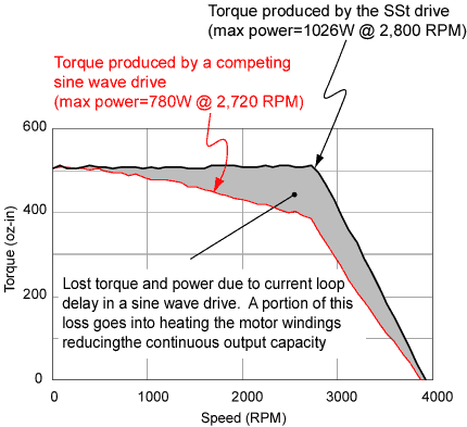
The effect of a misalignment in the electromagnetic vector is that the torque calculated by the main servo algorithm as necessary to achieve the desired velocity and position is not produced. Even simply under steady-state velocity and load conditions, the result of this progressive misalignment with respect to speed is a large "droop" in the torque-speed curve, as shown below.


Test conditions: 4 pole motor, Kt=25.4oz-in/A, R=0.65 @ 25 deg. C, windings held at 100 deg. C for all tests, 75VDC supply voltage, Sine amplifier and SSt drive set to deliver 23A peak. Dynamometer: Magtrol Model HD-705
Here, as in the Torque Response Time curves, it can be seen that basic sinewave servos are no longer state-of-the-art.


Current Control is not Torque Control—
The Torque-Speed Envelope

As everyone knows, energy can be neither created nor destroyed, so what happens to the current that goes into the motor but doesn't come out as torque? The misdirected current that causes magnetic misalignment and reduces torque, is converted to heat in the motor windings, thus reducing the motor's continuous torque capability.
More important than the steady-state torque disadvantages are the dynamic performance implications. Compounding the torque response delay discussed earlier, the magnetic field misalignment effectively lowers the main servo algorithm's gains, further reducing the position/velocity bandwidth. This retards dynamic response and increases tracking errors.

Closed-Loop Vector Torque Control
In contrast to simple current control, WorldServo's proprietary closed-loop vector torque control does not use a separate servo loop for each phase. Instead, it "de-rotates" the measured phase currents—in other words, converts them into one vector value (amplitude and phase)-and calculates the actual magnetic field vector. This vector, which is independent of motor speed and load, is then servo-controlled (as a vector) to remain in precise alignment with the magnetic field of the rotor. Therefore, the true torque can be accurately determined and accurately produced. Consequently, the torque command from the higher-level servo calculations is executed quickly and accurately for excellent servo performance (as can be seen in the earlier Torque Response Time graphs).
The exact control of the magnetic field also results in a flatter and broader torque-speed curve compared to other servos driving the same motor, and the measured curve looks very much like the theoretical curve, as you can see above. Peak power and efficiency are greatly improved because the losses within the motor are actively minimized. Furthermore, less wasted current means less heat, so you can use a smaller motor for any given application-reducing costs, machine size and power requirements.
Additionally, what's not evident from the torque-speed curve, is that by accurately controlling the magnetic field of the stator, torque ripple is virtually eliminated, as is its associated vibration. This gives you ultra-smooth motor rotation. (For linear motors, which are especially sensitive to commutation anomalies, the SST technology provides an even bigger advantage).


How the Simple Hall-Commutated Servo Compares

Comparing SST servo drives with a 6-step (Hall-effect sensor commutated) brushless drive is even more dramatic. In a 6-step drive, the current in each phase is not monitored. Only the total bus current amplitude is measured. This total is directed into the appropriate windings with a crude resolution of 60 electrical degrees by switching the phase voltages on and off as determined by the Hall-effect sensors that monitor the relative position of the rotor. The drive does not know the phase relationship between the individual winding currents—which is critical for orienting the stator's magnetic field—nor can it accurately produce the desired phase currents calculated by the servo algorithm because of its poor switching resolution.
These factors lead to inefficient and sub-optimal control. The magnetic field of the stator can end up virtually anywhere, particularly at higher speeds and with loads that have inertias larger than that of the motor. Additionally, the steady-state torque droop of this common type of drive scheme is significantly worse than the sinusoidal drive discussed earlier. This can be seen in the torque-speed curve below.


Test conditions: 4 pole motor, Kt=25.4oz-in/A, R=0.65 @ 25 deg. C, windings held at 100 deg. C for all tests, 75VDC supply voltage, 6-step amplifier and SSt drive set to deliver 23A peak. Dynamometer: Magtrol Model HD-705
Actual torque-speed curves of the same brushless motor driven by an SSt servo drive and a popular Hall-commutated drive. Notice that by simultaneously extending speed and torque, SSt servo drives produce nearly 2 to 1 advantage in peak power.


The beauty of the WorldServo SST servos is that all these benefits in performance stem from a careful choice of design architecture and from advanced control algorithms, not from brute force, expensive hardware "solutions." That's why the SST is actually less expensive that the competing solutions. (Note that although the SST is typically more expensive than a "dumb" (processor-less) 6-step drive, the system cost—including the controller—is lower. And that's what matters).

 Master Features/Benefits Menu