GD&T: Implementation Guidelines for Dimensional Tolerances
From WikiSTEP
Contents[hide] |
Associating Dimensions with Features or Geometry
Dimensional tolerances are attached to the items of geometry or topology that the dimension applies to. This is done by means of a subtype of the Shape_aspect_relationship Entity, i.e. dimensional_location, or by means of a dimensional_size entity. The identification of the type of tolerance is done via a specified string in the name attribute of the Dimensional Location or Dimensional Size entities.
- Note that Angular Dimensions are an exception to this, being defined by the Angular Location and Angular Size entities.
The mappings for the Dimensional Tolerance types to the required string are shown in Table 1 and Table 3.
Dimensional Location
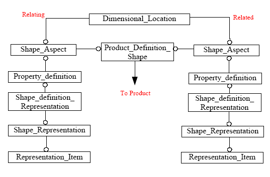
For the Dimensional_Location entity, the items between which the dimension applies are defined by shape_aspects. This is shown in Figure 1.
Figure 1. Attaching to Dimensioned Entities
'Note that the same structure is applied for the specialised subtypes of Dimensional Location, namely "Dimensional Location with Path" and "Directed Dimensional Location". The former of these provides a path for the measurement to follow by means of a shape_aspect (see Figure 4), the latter provides additional semantics to the Related and Relating attributes of the Dimensional Location, i.e. The measurement is to occur from the relating shape aspect to the related shape aspect.
Dimensions that map to a Dimensional_location are :
| Dimensional Tolerance | Dimensional Location.Name |
|---|---|
| Angular Location Dimension | N/A |
| Curved Distance Dimension | 'curved distance' |
| Linear Distance Dimension | 'linear distance' |
Table 1. Dimensional Location Types
Derived Shapes
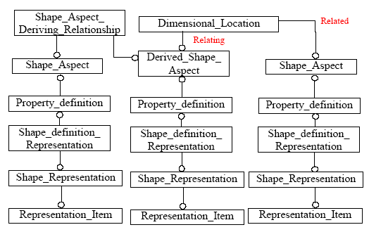
The preceeding figure (Figure 1) shows the attachment of the Representation Items that form either end of the Dimensional_Location to the Geometric or Topological entities at those points. In some cases, a Representation Item may not exist for that location in the model, e.g. The centre of a Hole , so in this case a " derived_shape_aspect" will need to be created to provide an anchor point.,. In these cases the additional Entities required are shown in Figure 2.
Figure 2. Derived Shape Aspect
Under certain conditions, a specialised subtype of the Derived_Shape_Aspect should be used. These conditions are listed in Table 2. Under any other conditions, the plain Derived_Shape_Aspect entity should be used. It is recommended, but not obligatory, that a meaningful string for the type of derivation be entered in the name attribute of this entity.
| Condition | STEP Entity Used |
|---|---|
| Apex of a Cone | APEX |
| Centre of a Symmetrical Feature | CENTRE_OF_SYMMETRY |
| Geometric Alignment of two Features | GEOMETRIC_ALIGNMENT |
| Perpendicular to Feature | PERPENDICULAR_TO |
| Spatial Extension to Feature | EXTENSION |
| Tangential to Feature | TANGENT |
| Parallel Offset from Feature | PARALLEL_OFFSET |
Table 2. Types of Derived Shape
Dimensional Size
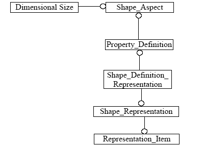
The Dimensional Size Entity is used where the measurement only applies to one object, rather than being a measurement between two distinct geometric or topological feature.
- Note that this one object can, under certain circumstances, be a composite of several shape_aspects. This will be illustrated in a later section.
Figure 3 shows how a Dimensional Size Entity is attached to the Representation Objects that it is a dimension of.
Figure 3. Dimensional Size
- Note that the same structure is applied for the specialised subtype of Dimensional Size, namely "Dimensional Size with Path". This provides a path for the measurement to follow by means of a shape_aspect (see Figure 4).
Dimensions that map to Dimensional Size are:
| Dimensional Tolerance | Dimensional Size.Name |
|---|---|
| Angular Size Dimension | N/A |
| Curved Size Dimension | 'curve length' |
| Diameter Size Dimension | 'diameter' |
| Height Size Dimension | 'height' |
| Length Size Dimension | 'length' |
| Radial Size Dimension | 'radius' |
| Thickness Size Dimension | 'thickness size' |
| Width Size Dimension | 'width' |
Table 3. Dimensional Size Types
Dimensional Location/Size with Path
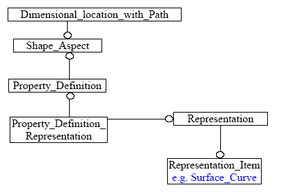
For some measurements, a path for the measurement needs to be defined, for example, when measuring the linear distance between two point on a curved surface. In this case, the measurement would need to follow the curve of the surface and not be the shortest straight line distance between the two points. In order to convey this information, this specialised subtype has an additional attribute, path, which points to a shape_aspect defining the path the measurement is to take. The instantiation of this is shown in Figure 4.
Figure 4. Dimension With Path
Application of Values to Identified Tolerances
Once you have identified the tolerance and attached it to the relevant pieces of geometry or topology as shown in the previous section, you can assign the tolerance value. The types of value that can be applied are:
- nominal value with a value limit
- nominal value with plus/minus bounds
- nominal value with value range
- limits and fits
Nominal Value with a Value Limit
In this case, a nominal value is applied to the dimension, i.e. A set value for the measurement, without any tolerance bounds. However, the value can be limited as to whether it is a Maximum value or Minimum value. There may be other limits allowed, and as the limit maps to a String in the Part21 Instantiation, there is no restriction on what value can be entered. For the present, I suggest that implementations limit this value to MAX or MIN as these are the only values which have set semantics.
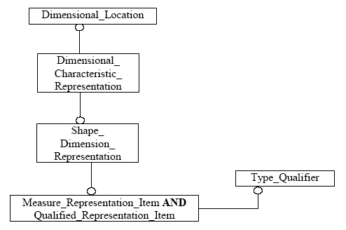
Thus for a nominal value, the actual value applied to the Dimension is conveyed by the value_component attribute of the Measure Representation Item, and the Limit on this value by the name attribute in the associated Type Qualifier Entity. Figure 5 shows the STEP entities used to instantiate this.
- Notes that the Dimensional Location referred to in the diagram could also be a Dimensional Size entity.
Figure 5. Nominal Value with Value Limit
Nominal Value with Plus/Minus Bounds
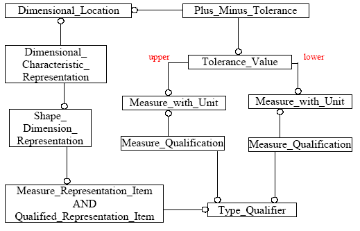
If a tolerance is represented as a Nominal value with a set of plus and minus deviations or bounds to that tolerance, then the entities shown in Figure 6 are used to instantiate the STEP File.
Figure 6. Value with Plus/Minus Bounds
For this instantiation there are some points to note. The Type Qualifier " Name" attribute, used to denote MIN and MAX in Nominal Value with a Value Limit, in this case takes the value 'designed' in order to convey the fact that the Tolerance applied is the 'as designed' tolerance. It can take the values: 'required', 'calculated', 'measured' and 'estimated' in addition to 'designed', but the semantics of these are unclear at present.
The Values of the Plus/Minus Tolerance are found in the Measure With Unit Entities referred to by the upper and lower attributes of the Tolerance Value Entity.
- Note that for clarity, even though it is given that the Tolerance Value is an upper or lower limit, the value should still be given as an offset from the Nominal. e.g. The Lower Limit should be a Negative number and the upper limit a Positive Number.
Nominal Value with Value Range
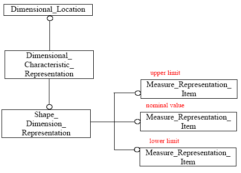
An alternative way of presenting, rather than representing the dimension, is as a range of values that is the extents of the tolerance applied. As originally mapped in the Standard, this would give two values, one for the upper limit and one for the lower limit. Upon implementation, however, it was found that the majority of CAD systems hold the tolerance value as a nominal, with a plus/minus deviation, and handle the presentation of this data seperately, thus the lack of a nominal value through this method caused problems for reimporting the data, as this value was lost. In order to alleviate this, a third value, representing the nominal value was added to the mapping.
The STEP instantiation of this is shown in Figure 7.
Figure 7. Nominal Value and Value Range
To determine which of the Measure Representation Items denotes which value, they shall be identified by one of the following strings used for the name attribute : 'nominal value', 'upper limit', 'lower limit'.
Limits and Fits
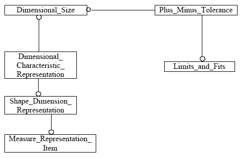
The implementation of a limits and fits tolerance is fairly easy. What is not immediately apparent is the meaning of the tolerance. The Limits and Fits designation is closely linked to the Tolerancing Standard applied for the file, as it references a table of standard tolerances maintained within that standard.
Figure 8 specified the STEP entities used to carry this information in an exchange file.
Figure 8. Tolerance as Limits and Fits
Applying Number of Decimal Places
The displayed value of the Dimensional Tolerance can be truncated to a number of decimal places, by specifying a Precision Qualifier to the Representation Item which hold to tolerance value. This is done using a complex entity for the Measure Representation Item, containing the Qualified Representation Item entity, which in turn, points to a Precision_Qualifier, which specifies the number of decimal places by it's precision_value attribute.
Figure 9. Decimal Precision Qualifier
