Lesson 5
Mastercam x2 basics
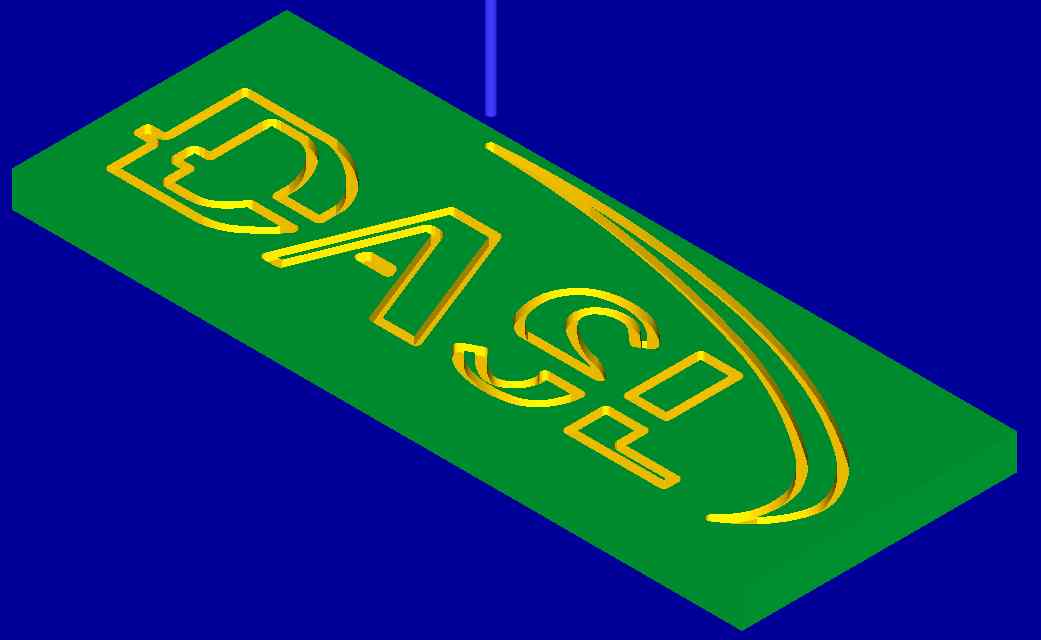
FIGURE 1
![]() Lesson 5 introduces NC code generation with Mastercam X2.
Computer-aided Manufacturing (CAM) mixes Computer-aided Design (CAD)
with manufacturing techniques to create an efficient and automated NC
code generator.
Lesson 5 introduces NC code generation with Mastercam X2.
Computer-aided Manufacturing (CAM) mixes Computer-aided Design (CAD)
with manufacturing techniques to create an efficient and automated NC
code generator.
Section 1 - Overview
Section 2 - Menu Navigation and Part Setup
Section 3 - Path Layout
Section 4 - NC Simulation and Generation
Section 1 - Overview
![]() Mastercam X2 software is a CAM product made to make NC code generation
faster an
more efficient. This tutorial and following project requires CAD
experience. Reference DASL software library to acquire proper CAD
software. This tutorial will supply STEP files that are to
be used
to generate the examples.
Mastercam X2 software is a CAM product made to make NC code generation
faster an
more efficient. This tutorial and following project requires CAD
experience. Reference DASL software library to acquire proper CAD
software. This tutorial will supply STEP files that are to
be used
to generate the examples.
If MasterCAM X2 requires HASP USB dongle to run the software the DASL single seat. The seat is installed on the the computer located in the Office in Bossone 107. Plugged into the computer is this HASP dongle, this dongle stays with this computer unless is cleared to be moved by Robert Ellenberg or Roy Gross. The dongle must be plugged into the computer upon boot and if removed during operation will lock the use of Mastercam X2.
Under START menu Mastercam is listed under Mastercam X2 MR2
Section 2 - Menu Navigation and Part Setup
![]() Click
Menu Navigation to view a screen shot and labels of the Main
dashboard
Click
Menu Navigation to view a screen shot and labels of the Main
dashboard
Follow the following steps to set up the Fouth Example that is the same from lesson 1. These steps should be followed each time for setting up a STEP file.
Along the top are the generic menus (file, edit...etc.). Find Machine Type > Mill > Default. Clicking this a new feature will appear in the Toolpaths Manager "Machine Group-1". Click here to download Example1.STEP. File > Open > Set "files of type" to STEP Files (*.STP;*.STEP) . Select file from download location and click the green check mark. Now the wire frame diagram located at Origin. Under Views click the green wire cube that is not filled in (Isometric View). Now click the blue sphere that was labeled as Wire/Solid and then click the Center icon, both of these are labeled in "Menu Navigation" Then Click Properties - Generic Mill > Stock setup. This sub-menu " Machine Group Properties" should be used to define the region or "stock" dimensions so Mastercam knows it's working bounds. Click the All Solids button, check to see if the dimensions are correct and then press the green check button. Notice the stock bounds will show up as a red dotted Rectangle around the CAD. Remember this represents the "real" un-machined stock that the machined part will be created from.
Section 3 - Path Layout
![]() This section will outline the basics to create the CAM tool paths to
machine
Lesson 1
example 4 part . In the introductory example 4 a 1/2inch Flat end mill
was used.
For this example a 1/4inch Flat end mill will be used. The NC code
from lesson
1 example 4 only cuts out the "island" but does not take care of the
reaming
stock to make a complete part. Rerun NCPlot example 4 code to check this
out.
To make this a complete part there will be two groups of tool
passes. One
will Contour the curve in the Island and the other will eliminate the
reaming
material.
This section will outline the basics to create the CAM tool paths to
machine
Lesson 1
example 4 part . In the introductory example 4 a 1/2inch Flat end mill
was used.
For this example a 1/4inch Flat end mill will be used. The NC code
from lesson
1 example 4 only cuts out the "island" but does not take care of the
reaming
stock to make a complete part. Rerun NCPlot example 4 code to check this
out.
To make this a complete part there will be two groups of tool
passes. One
will Contour the curve in the Island and the other will eliminate the
reaming
material.
To start go to the menu bar and find Toolpaths > Contour Toolpath...
> a dialog
box ill appear, click the green check > "Chaining" sub menu should
appear. The
following steps will be circles in red in the figure 2.
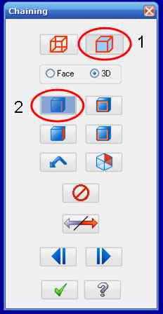
FIGURE 2
Click the Red wire frame that is filled in blue (Solids). The sub
menu
should change then click the blue box with the red edge button. Now
click the
round edge that is shown below in figure 3. The edge of the should turn
blue and
a green arrow should also appear on the edge and click the green check
mark to
complete the contour setup. A new menu should appear "Contour (2D)" .
Now find
"Select library tool..." button located on the "Toolpath parameters" tab
and
another menu should appear make sure MILL_INCH.TOOLS is selected. Find
tool 235,
click to highlight blue and then click the green check mark . Find feed
rate,
plunge speed, Spindle speed, and retract rate. Leave as the
Default F
6.4176 and S 2139; these are the DRO inputs that will be changed to
adjust the
feeds and speeds depending on material. Click the "Contour parameters"
tab and
uncheck the the box next to "Retract...". Retract is used to lift the
tool above
the part after each pass, removing cuts down machining time. "Top of
stock..."
should read 0.0 and "Depth.." should read -0.1 if not then click the
"Depth.."
button and position the + curser over a corner that joins the base of
the island
and the reaming stock surface shown in figure 3. To test this cut to see
if it
was constructed correctly click the Toolpath Manager > "Verify the
selected
toolpaths" (purple solid icon). The screens should change and a window
called
"verify" should appear. There is a slider bar between a a black
person
walking and a red person running, place the slider in the center to
control the
speed. Then press the black triangle (>) to run the machining
simulator.
There is rewind option to view again (double back arrow |<<). To
exit press the
green check. If everything looked like it worked as planed move on to
next path.
If it did not, to edit click the toolpaths manager and click on
"Parameters". To
set up the next tool path follow the same steps to get to Contour sub
menu.
After each edit the toolpaths become "dirty" and cannot run the
simulation until
fixed. To fix it click the toolpath manager and click the button that
looks like
a tool with a red X next to it (Regenerate all dirty operations). Next
Click the
red wire frame that is not filled in shown in figure 4. Click the
button
that has a single red diagonal line show in figure 4.
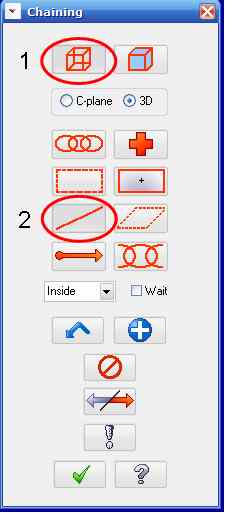
FIGURE 4
Now click each edge of the block as shown in figure 5 the edged should
turn
yellow. Click green check mark and "Contour 2D" should appear. Use
the
same selected tool. Go to the second tab and set the same as last
contour but
change the drop down menu "Compensation Direction:" from Left to Right.
No run
the simulation as previously stated. Notice that it only
runs the
edge material removal (last path generated) . To show
manufacturing of
entire part, click the toolpath Manager and click "select all
operations"
button, it is a green check mark with a green arrow next to it. After
you verify
the correct paths are generated, Complete CAM, the next step is to
generate the
usable NC code. Click the toolpath manager and click the button that is a
blue
G1. A window named "Post Processing" appears and press the green check
mark.
Then the "Save As" window appears, rename (Example4) and location is
based on
user. After saving the Mastercam X Editor should maximize to full
screen.
Now the code is now in raw NC code to be edited. Line number 162
and 164
should be deleted, issues arise when running Mach3 interpreter.
Also if
this was going to be machined M8/M9 would have to be added as taught in
Lesson
1. Copy completed code and paste it into CNC simulator and
verify
with the code below.