Lesson 4
Tormach PCNC
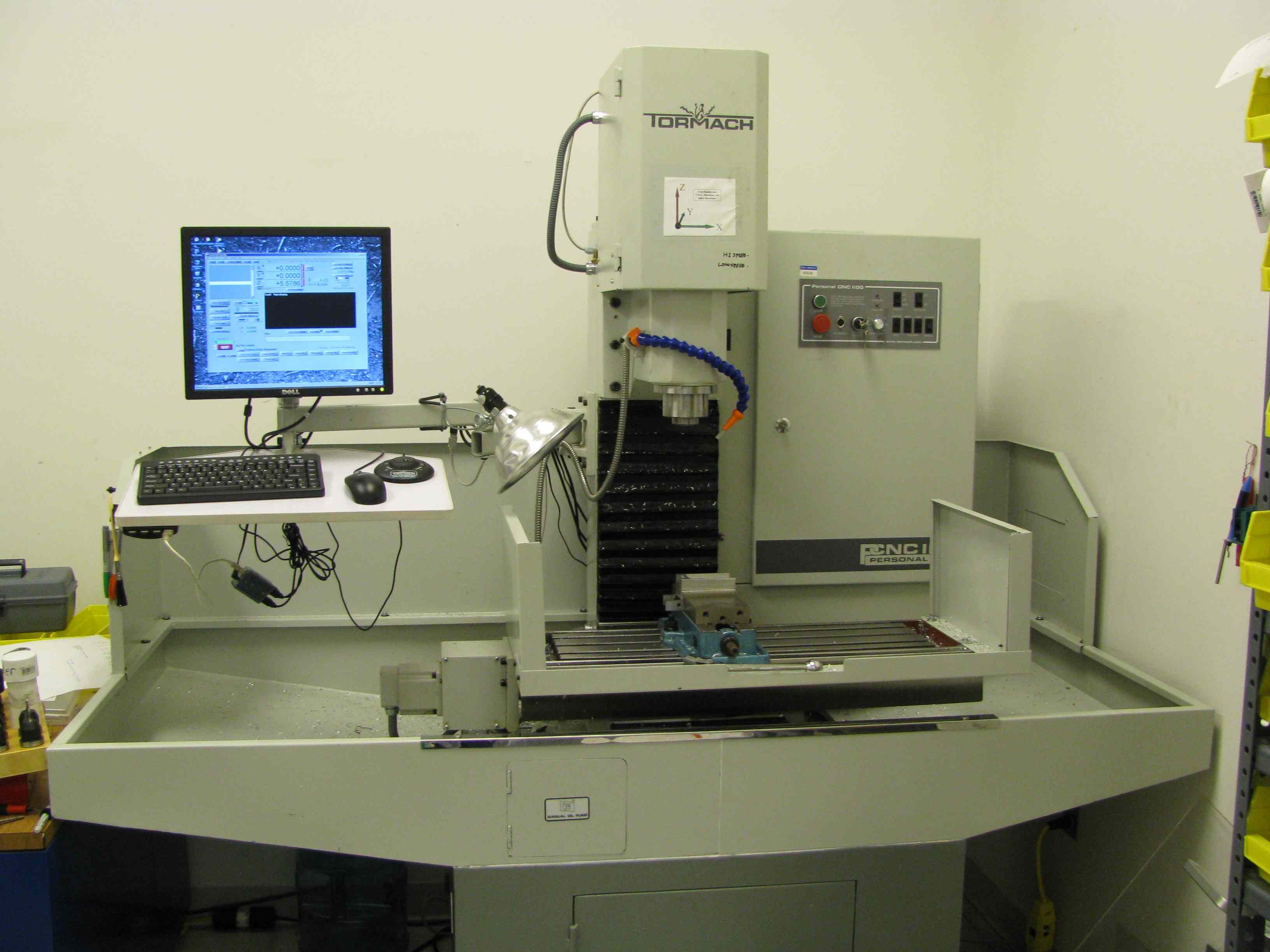
FIGURE 1
![]() Lesson 4 provides incite into DASL specific Tormach PCNC setup.
The
below are the topics to be covered in this section. This
tutorial
is largely based on the
HAAS Workholding & tooling tutorial.
Lesson 4 provides incite into DASL specific Tormach PCNC setup.
The
below are the topics to be covered in this section. This
tutorial
is largely based on the
HAAS Workholding & tooling tutorial.
Section 1 - Workholding
Section 2 - Setting Offsets
Section 3 - PCNC Mach 3 CNC Controller
Section 1 - Work Holding
Prereading: Tormach PCNC 1100 Operator’s Manual, Section 6.1-6.3, 6.5
![]() First, a note of caution: Before placing any type of workholding on your
machine
table, be sure that the table is CLEAN and free of chips and other
debris. Chips
and other debris caught between a fixture and the machine table will
damage
both. Swarf caught between the fixture and table can cause the fixture
to rock,
and the parts machined will be inaccurate. Also make sure that whatever
you set
on the table is clean and free of debris.
First, a note of caution: Before placing any type of workholding on your
machine
table, be sure that the table is CLEAN and free of chips and other
debris. Chips
and other debris caught between a fixture and the machine table will
damage
both. Swarf caught between the fixture and table can cause the fixture
to rock,
and the parts machined will be inaccurate. Also make sure that whatever
you set
on the table is clean and free of debris.
Always rub the locating surface with a honing stone. This will ensure that the locating surface does not have any burrs or dings that may damage the table. If you plan to leave your workholding on the table for any length of time, a light coat of rust-preventive oil or WD-40® will help keep your table and workholding free of rust and corrosion.
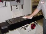
The first thing to determine when you're setting up a CNC mill is how you want to hold the workpiece on the machine. There are three basic types of workholding used in milling operations: vises, clamps, and chucks. The most common method of holding a workpiece for machining is a mill vise. For precision work, the vise must be set so that the clamping surfaces are parallel to the X or Y axis. This is done using an indicator. The following simple procedure makes it quick and easy to indicate a mill vise.
1. Set the mill vise on the table and put your T-nuts and bolts in position.
2. Tighten the bolt on the right side of the vise and just "snug" the bolt on the left side.
3. Place the magnetic base anywhere on the bottom of the Z-axis head. To ensure that the indicated readings are accurate, the magnetic base should be mounted on a solid, non-movable part of the head. Jog the machine axes to bring the indicator tip to the right side of the vise, on the clamping surface you want to indicate. Set the tip of the indicator so it begins to register on the indicator dial and set zero.
4. Jog the indicator across the clamping surface and stop at the left side of the vise. Determine which direction the vise needs to be moved, and tap the vise until your indicator moves back to zero. Note: with the right bolt tight, the vise will rotate around this point. Jog the indicator back to the right side of the vise, and reset zero. Jog back to the left side and tap the vise until your indicator reads zero. You should be very close by now. Repeat the previous steps until the indicator stays at zero across the entire indicating surface.
5. When the indicated reading is perfectly flat across the vise jaw, tighten the left bolt first, then tighten the bolt on the right side. Run your indicator across the surface one last time to make sure it is still parallel with the machine travel.
TIP: Use a soft or dead blow hammer to tap the fixture or vise into position. Using a ball peen hammer or other hard object may damage the fixture.
Make sure, when locating a part in a mill vise, that you center your part in the vise. You don't want a large portion of the workpiece hanging off the side of the vise. This will cause the movable vise jaw to twist and pinch the workpiece, greatly reducing the clamping force. If you try to drill a hole in the overhanging material, the Z-axis thrust may cause the material to push down at the drilling point and push up on the other side of the workpiece.
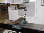
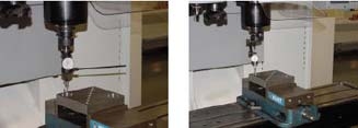
If it is necessary to drill through a workpiece that is held in a vise, use parallels (XXX).or step jaws.
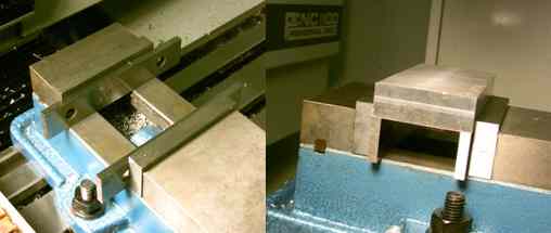
FIGURE 1 - USING PARALLELS FOR DRILLING THOUGH HOLES IN WORK
They allow you to locate the workpiece up, off the bottom of the vise. This will provide clearance below your workpiece so you can drill through without drilling into the vise. If you only have hardened steel jaws without a step cut in them, you can use a set of parallel bars inside the vise to set the workpiece on to keep it off the bottom of the vise. Always verify that the parallel bars are the same size to ensure that your workpiece is sitting flat
TIP: Most precision mill vises have a key slot and keys on the locating surface. You can use the keys on the vise to locate it in the mill table’s T-slots. This will locate your vise square to the table. If your vise doesn't have keys, you can make a sub-plate for the vise with keys or dowel pins on the bottom to locate in the T-slots. On the top, you can cut holes for attaching the sub-plate to the machine table, and tap holes for attaching the vise to the sub-plate. Locate the sub-plate in the T-slots and bolt it to the table. Set the vise on the sub-plate and indicate it as described above. Now, every time you use that vise, just locate the sub-plate in the T-slots, bolt it down, and you're ready to go. For high-precision work, you will still have to check the indication and make small adjustments.
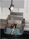
When using clamps to hold a part with downward force, ALWAYS make sure that the clamp is lower where it contacts the part and higher in the back. Most downward-force clamps use a jackscrew or serrated block that meshes with serrations on the clamp, to support the end of the clamp opposite the end making contact with your part. The serrated end of the clamp must be higher than the contact end of the clamp.
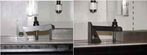
FIGURE 2 - INCORRECT (LEFT0 AND CORRECT (RIGHT) USE OF STRAP CLAMPS
If it is not higher, the clamp will make contact with the edge of your part and not the top. This will greatly reduce the amount of clamping force holding the part, and probably create a dent at the intersection of the top surface and the side surface of the part. If you use the jackscrew style clamp, make sure that the jackscrew does not sit directly on the mill table. Always use a thick piece of shim stock or other material to protect the mill table from damage.
When clamping on a cylindrical surface is required, a 3-jaw chuck can hold the stock perpendicular to the table for easy end drilling.
Section 2 - Setting Offsets
![]() In many cases, a CNC programmer has defined Z zero in the program to be
at the
top of raw stock. Quite often, though, raw stock is not flat or
perfectly
parallel to any axis.
In many cases, a CNC programmer has defined Z zero in the program to be
at the
top of raw stock. Quite often, though, raw stock is not flat or
perfectly
parallel to any axis.
TIP: If you need to set tool length offsets from the top of raw stock but need to have precise measurements on your tool lengths, take a light skim cut on the stock. Now you can measure your cutters from a flat, clean surface. Or you can set the tool length offsets from the fixture where the part will be sitting, then increment the Z-axis work coordinate offset to a positive value equal to the thickness of the part.
Consult the Tormach PCNC1100 manual (Section 6.2) for more information on zeroing a part.
When setting work coordinate offsets, you must locate X zero and Y zero accurately. Remember that you are measuring the centerline of the spindle to a location on a part or a fixture. If it is the edge of a part or fixture, an edge finder is the most common tool used.
An edge finder is composed of two concentric cylinders, spring-loaded together. To use it, place the edge finder in a collet chuck and offset the two halves slightly, so that there is a wobble as it spins. Then, slowly jog the part into the wobbly end of the edge finder. The edge finder will center up, and then break out of concentricity suddenly. At that point, jog the edge finder in the positive Z direction to raise it above the workpiece.
TIP: If you are setting your TLO from the part, you will only need to set the work coordinate offset for the X and Y axes. The Z-axis work coordinate offset will be compensated for by the tool length offsets.
TIP: 1000-1500 rpm is a good spindle speed range when using an edge finder.
If you need to find the centerline of a hole or a round part feature, an Indicol is a helpful tool. This is a type of holder for dial-test indicators. It has a C-style clamp to attach the Indicol to a tool holder in the machine spindle. The Indicol also has two or three adjustable arms and a clamp at the end to hold a dial test indicator. The adjustable arms allow you to position the indicator to spin the same diameter as the hole.
To find the centerline of a hole, position your indicator tip just above the hole and manually spin the tool holder with the Indicol attached. You will be able to see if your indicator tip is spinning the same approximate diameter as the hole and how far off-center your current position is. Adjust the X and Y axes as close as possible before moving the indicator down into the hole. Once they're close, jog the Z axis down so the indicator tip is inside the hole, and adjust the arms so that the indicator begins to give a reading. Spin the indicator so that it is making contact with the surface of the hole in one of four quadrants (X+, X-, Y+, or Y-). Now, set the indicator to zero and rotate it 180 degrees. The amount of indicator movement is 2X the amount of axis adjustment needed. If your indicator moves minus 0.016, then you need to jog the axis 0.008 in the plus direction.
Now, rotate your indicator 90 degrees and reset zero. Rotate the indicator 180 degrees to find the amount and direction in which the other axis needs to be adjusted. Remember, the distance the indicator moves is 2X the distance that you will have to jog the axis to find the centerline of the hole. This procedure can be tricky on small diameter holes, but it is very accurate. You really can find the exact centerline of a hole, within 0.0001 of an inch, in each axis.
TIP: A huge time saver for finding the center of a hole or round part feature is a coaxial indicator. This indicator fits into a collet chuck, and you use it while the spindle is turning. Manufacturers claim that you can use these indicators at speeds up to 800 rpm, but the 50 to 100 rpm range works well; if the spindle is rotating too fast, it is difficult to tell which axis needs to be adjusted. A restraining arm allows the face of the indicator to remain stationary while the spindle rotates. With each rotation of the spindle, the indicator dial will show the amount it is off-center. You simply jog the machine axes while watching the indicator movement. This saves time because you can start the rotation while the indicator is off-center by as much as 0.250 inch, and you can literally dial it in within seconds.
Section 3 - PCNC Mach 3 CNC Controller
![]() Simple Run Terminal:
Simple Run Terminal:
To view the simple run terminal click thumbnail below. The thumbnail is accompanied by descriptions in below as well. The picture features are separated by number located in orange circles on the image.

1. OpenG - Opens a new file (types: .tap, .nc, .ncc, .txt, All files)
2. NC code Browser- Scroll and view only the NC code
3. Cycle Start - Beings the execution of loaded code
4. Stop - Soft stop only halts executing code (Not a replacement for
E-Stop
which kills all machine functions)
5. Rewind - resets code in Browser to file the beginning (similar to
manual M30)
6. Coolant - Manually starts coolant; to start press once to turn on and
press
again to stop flow. (similar to M8/M9 combo)
7. Reset - If machine is interrupted by a limit overrun or E-stop the
Reset
needs to be pressed once.
8. Reset Indicator - This long rectangular bar flashes red and green
when one of
the above circumstances happens. Also a warning message scrolls to
show
error.
9. Change G-Code - Opens a sub menu and gives the option to open file in
Notepad
to edit code. After editing save and exit NotePad. Mach 3 will check the
file
for errors then re-open it in Browser (2)
10. Zero X Y Z - The rectangular buttons set the displays to
the
right of the buttons to zero. During machining these displays show
the
specified G90 Cartesian motions.
11. Spindle CW - Manual operation of spindle; to turn on press once to
turn off
press again. (similar to M3/M5 Combo) The indicator is separated into 3
yellow
sections. When spindle is one middle indicator blinks. When machine is
shutting
down the spindle the outer two blink. This is also accompanied with a
delay to
operate other Mach 3 controls.
12. MDI: - Manual command input allows the user to execute NC code that
is not
in Browser file. Example: G0 X0 Y0
13. This space displays more information regarding the E-stop and file
location
information.
14. Ref All - Reference all axis to Home position. This should be used
at the
when starting up the machine. Warning: Ref resets all zeroed
coordinates - so don't use after E-Stop if not needed. (used
with M998
to work properly)
15. F - Feed value used with max-jog or keyboard or MDI is used to move
any
axis. This value defaults to the Feed rate that is stated in NC code
when being
executed. To edit, clicking turns input white and type new value
if needed
for a new manual operation rate.
16. Step - This value is used by inner wheel or step wheel on jog pad.
This is
edited the same way as the jog input.
17. Simulation Window - When code is loaded the "NCplot style" of the
code is
displayed. During operation of code the XYZ position of tool and table
can be
tracked. To operated the Window click once. Then use the roller wheel on
mouse
to zoom in. To rotate in 3D, click and drag to desired position. Once
Rotated
the window can not be reset top XY default. Also during machining
operation the
window becomes inactive and can not be operated by user. (Remember to
make all
adjustments before you start!)