Lesson 3
machining mill tools & operations

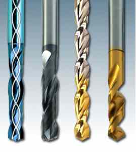
FIGURE 1
![]() Lesson 3 explains different tools/purposes, cutting operations,
and
proper work/camping setup. In figure 1 shows the main tools/holders in
DASL Index. This tutorial is largely based on the
HAAS Workholding
&
tooling tutorial.
Lesson 3 explains different tools/purposes, cutting operations,
and
proper work/camping setup. In figure 1 shows the main tools/holders in
DASL Index. This tutorial is largely based on the
HAAS Workholding
&
tooling tutorial.
Section 1 - Tool Holders
Section 2 - Cutting Tools
Section 3 - Operations
Section 1 - Tool Holders
![]() Selecting the right tool holder for the job is as important as selecting
the
right cutter for the job. You should always use the shortest tool holder
possible for all machining applications. In addition, the tool should be
set
into the tool holder as far as possible. This will increase the tool
holder's
grip on the tool and reduce vibration. The shorter the distance from the
spindle
nose to the tool tip, the more rigid your setup will be. Increased
rigidity
means less vibration when cutting.
Selecting the right tool holder for the job is as important as selecting
the
right cutter for the job. You should always use the shortest tool holder
possible for all machining applications. In addition, the tool should be
set
into the tool holder as far as possible. This will increase the tool
holder's
grip on the tool and reduce vibration. The shorter the distance from the
spindle
nose to the tool tip, the more rigid your setup will be. Increased
rigidity
means less vibration when cutting.
For more information on toolholder design and varieties , please consult
the
Tormach
Tooling System Manual: Page 4
Section 2 - Cutting Tools
![]() When selecting cutting tools for a job, the first thing to consider is
what type
of operation needs to be performed. Here is a quick description of the
basic
cutting tools most often used in milling operations.
When selecting cutting tools for a job, the first thing to consider is
what type
of operation needs to be performed. Here is a quick description of the
basic
cutting tools most often used in milling operations.
Drill
A twist drill is used to create a round, cylindrical hole in a
workpiece.
Drilled holes can be "through holes" or "blind holes". A "blind hole" is
not cut
entirely through a workpiece. Quite often, an engineering blueprint will
specify
a drilled hole to be drilled to "full diameter depth." This means that
the hole
diameter must be a specified depth without regard to the angled tip of
the
drill. When you measure your tool length offset, you are measuring the
length of
the drill and its tip. So how deep do you drill the hole so that the
full
diameter depth is correct? Well, you need to know how long the drill
point is.
TIP: The length of the drill point
is
determined by the tool point angle and the drill diameter. You can
calculate the
length of the drill point by multiplying the drill diameter by a
constant; the
value of the constant depends on the drill point angle (most standard
high-speed
steel drills have a tool point angle of 118 degrees).
| For a drill point angle of | Multiply the drill diameter by: |
| 118 degrees | 0.3 |
| 135 degrees | 0.207 |
| 141 degrees | 0.177 |
Using these constants allows you to calculate the drill point length within a few thousandths of an inch.
Spotting Drill
![]() Drills with a standard point (Figure 3) will not be able to center
themselves
when starting a hole. Especially when drilling an uneven surface (like a
cylinder), the drill can “walk” to one side and even break.
Drills with a standard point (Figure 3) will not be able to center
themselves
when starting a hole. Especially when drilling an uneven surface (like a
cylinder), the drill can “walk” to one side and even break.
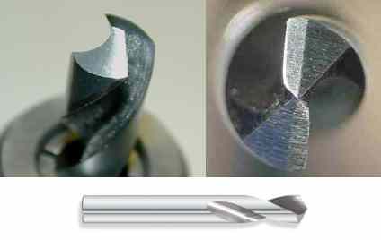
Figure 3 - A STANDARD POINT DRILL (LEFT) VS. A SPLIT POINT DRILL (RIGHT)
SIDE
VIEW STANDARD (BOTTOM)
Therefore, when using a standard point drill, always use a spotting drill to make a starting mark. The spotting drill ahs shorter flutes & a narrower tip than a standard drill, allowing it to make an accurate impression in the work. The standard drill then starts in that impression, producing an accurate hole.
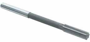
Reamer
![]() A reamer is designed to remove a small amount of material from a drilled
hole.
The reamer can hold very close tolerance on the diameter of a hole, and
give a
superior surface finish. The hole must be drilled first, leaving 0.005
to 0.015
inch of stock on the walls of the hole for the reamer to remove.
A reamer is designed to remove a small amount of material from a drilled
hole.
The reamer can hold very close tolerance on the diameter of a hole, and
give a
superior surface finish. The hole must be drilled first, leaving 0.005
to 0.015
inch of stock on the walls of the hole for the reamer to remove.
TIP: The ideal situation for hole size accuracy and location when reaming is to process the hole with the following steps: the hole is first drilled, then bored, then reamed.
TIP: Stock allowance for a reamed hole will depend on the size of the hole. A general rule is:
| Holes less than 1/2" | Holes greater than 1/2" |
| Stock less than 0.015" Dia. | Stock of 0.030" Dia. |
The type of workpiece material and the method used to create the hole will affect the stock allowance.
TIP: A reamer produces the best, most uniform surface finish when it is fed into and out of the hole using the G85 (bore in, bore out) canned cycle. Many people try to save time by using the G81 (drill) canned cycle, which will feed into a hole and rapid out. It is quicker than G85, but will usually leave a helical swirl mark on the cylindrical surface of the hole. Although this swirl mark is only a cosmetic flaw and doesn't affect the size of the hole, the appearance of the hole may be rejected by some customers.
Tap
A tap is used to create screw threads inside of a drilled hole. While Automatic Tapping heads for milling machines can automate the tapping of holes, tapping is most cheaply done by hand.
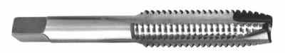
TIP: Tap drill size is the size of the hole required for a specific tap. For 75% effective threads the formula that will determine the correct drill size is:
D – 1/N, where D = major diameter of the tap and N = number of threads per inch
A tapped hole with 75% of thread depth has only 5% less strength than 100% thread and takes only 1/3 of the cutting force of a 100% thread.
End Mills
![]() End mills are used for many operations, and come in a variety of shapes
&
sizes.
End mills are used for many operations, and come in a variety of shapes
&
sizes.
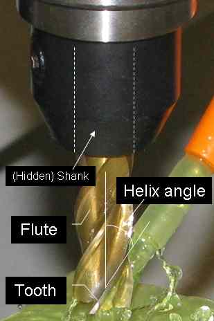
Regular or Flat End Mill
![]() Most generic end mill that can be used for many tasks. Bellow is
the
labeled parts of end mills.
Most generic end mill that can be used for many tasks. Bellow is
the
labeled parts of end mills.
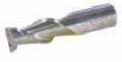
Bull End Mill
![]() A bull end mill is the same as a regular end mill except that there is a
radius
on the corner where the flutes meet the bottom of the end mill. This
radius can
be any size up to one-half of the tool's diameter.
A bull end mill is the same as a regular end mill except that there is a
radius
on the corner where the flutes meet the bottom of the end mill. This
radius can
be any size up to one-half of the tool's diameter.
TIP: Bull end mills are effective for producing a corner radius between a wall and a floor on a given part feature. They also add to the strength of an end mill. When machining hard, tough to cut materials, the sharp corners on a standard end mill tend to chip and wear faster than an end mill with a corner radius. The radius on a bull end mill provides a more gradual shearing entry in to the work piece.
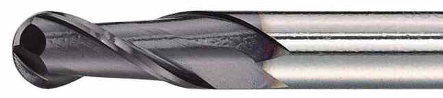
Ball End Mill
![]() A
ball end mill is a bull end mill where the corner radius is exactly 1/2
the
tool's diameter. This gives the tool a spherical shape at the tip. It
can be
used to cut with side of the tool like an end mill.
A
ball end mill is a bull end mill where the corner radius is exactly 1/2
the
tool's diameter. This gives the tool a spherical shape at the tip. It
can be
used to cut with side of the tool like an end mill.
TIP: The primary purpose of a ball end mill is to machine lofted surfaces. The spherical shape of the tool is able to move along any undulating surface and cut anywhere along the cutter's "ball end." As a ball can roll over a surface, a ball end mill can be used to cut any such surface.
Special Purpose Tools
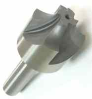 |
Corner
-Corner-Rounding End Mill This end mill has a concave tip radius which allows it to round outside edges of work. It can also flare holes, provided the hole is wider than the nose. |
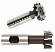 |
Keyseat /
T-slot
Cutter Much like a small saw blade, the teeth of this cutter can cut precise slots more quickly than an end mill. It is used to make keyseats for woodruff keys. Larger versions can be used to cut T slots. |
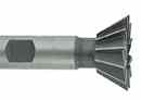 |
Dovetail
Cutter The 45° or 60° sides of this cutter are used to sidemill dovetails into a work piece. |
|
|
Drill Mill /
Angle End Mill The angled tip of this end mill can be used to chamfer edges, countersink holes, or make shallow grooves. The tip usually has an 82°, 90°, or 100° included angle for countersinking different kinds of flathead screws. |
Section 3 - Operations
Slotting
![]() The most common operation for an end mill is slotting (Figure 4).
A single axis move brings the tool into the work, creating a channel
close to
the width of the tool.
The most common operation for an end mill is slotting (Figure 4).
A single axis move brings the tool into the work, creating a channel
close to
the width of the tool.
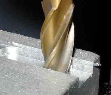
FIGURE 4 - SLOTTING ALUMINUM WITH AN END MILL
To perform this operation properly:
· Choose a depth of cut no greater than the diameter of the tool
· Use a 2-flute end mill for deep cuts to evacuate chips more easily
· Use coolant for heavy cuts to evacuate chips
Side milling
![]() Any cut using primarily the sharp sides of a milling cutter (end mill,
shell
mill, etc.) is referred to as side milling. With the right combination
of feed &
speed, side milling can produce a finer finish than end milling, since
the
motion of the tooth is more uniform across the work piece.
Any cut using primarily the sharp sides of a milling cutter (end mill,
shell
mill, etc.) is referred to as side milling. With the right combination
of feed &
speed, side milling can produce a finer finish than end milling, since
the
motion of the tooth is more uniform across the work piece.
Most side milling on small machines is performed with an end mill. Cutting forces are higher due to the large area being cut. As such, depth of cut needs to be reduced, and should never exceed the radius of the cutter. Deep & heavy rough cuts will tend to bend the tool away from the work, which makes the cut shallower at the tip of the tool than at the base. Finish passes of about .005” to .010” depth of cut should be used to ensure a perpendicular edge.
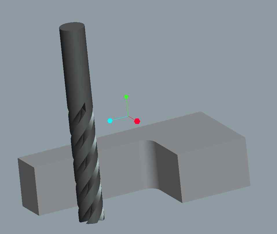
Pocketing/Profiling
![]() End mills can also be used to create pockets in a work piece. On a
manual
machine, pockets can be cut only in rectangular/circular shapes.
The precise
control of the X & Y axes on a CNC mill allows pockets of any shape
to be cut
(figure 5). The tool can be fed into the work in either the Z
axis, or one of
the transverse axes. If the end mill is plunged fully into the
work, and then
moved in X& Y axes, then the sides of the teeth perform most of the
cutting. By
taking shallower plunges & larger stopovers, more of the cutting is
performed by
the ends of the mill. Due to the changing directions of cutting
forces during
roughing, a finish pass is necessary to produce a precision surface.
End mills can also be used to create pockets in a work piece. On a
manual
machine, pockets can be cut only in rectangular/circular shapes.
The precise
control of the X & Y axes on a CNC mill allows pockets of any shape
to be cut
(figure 5). The tool can be fed into the work in either the Z
axis, or one of
the transverse axes. If the end mill is plunged fully into the
work, and then
moved in X& Y axes, then the sides of the teeth perform most of the
cutting. By
taking shallower plunges & larger stopovers, more of the cutting is
performed by
the ends of the mill. Due to the changing directions of cutting
forces during
roughing, a finish pass is necessary to produce a precision surface.
Contour
This the process of milling an ill regular surface. This can simply creating an island as seen below in figure 5 or milling more complex curves like letters.
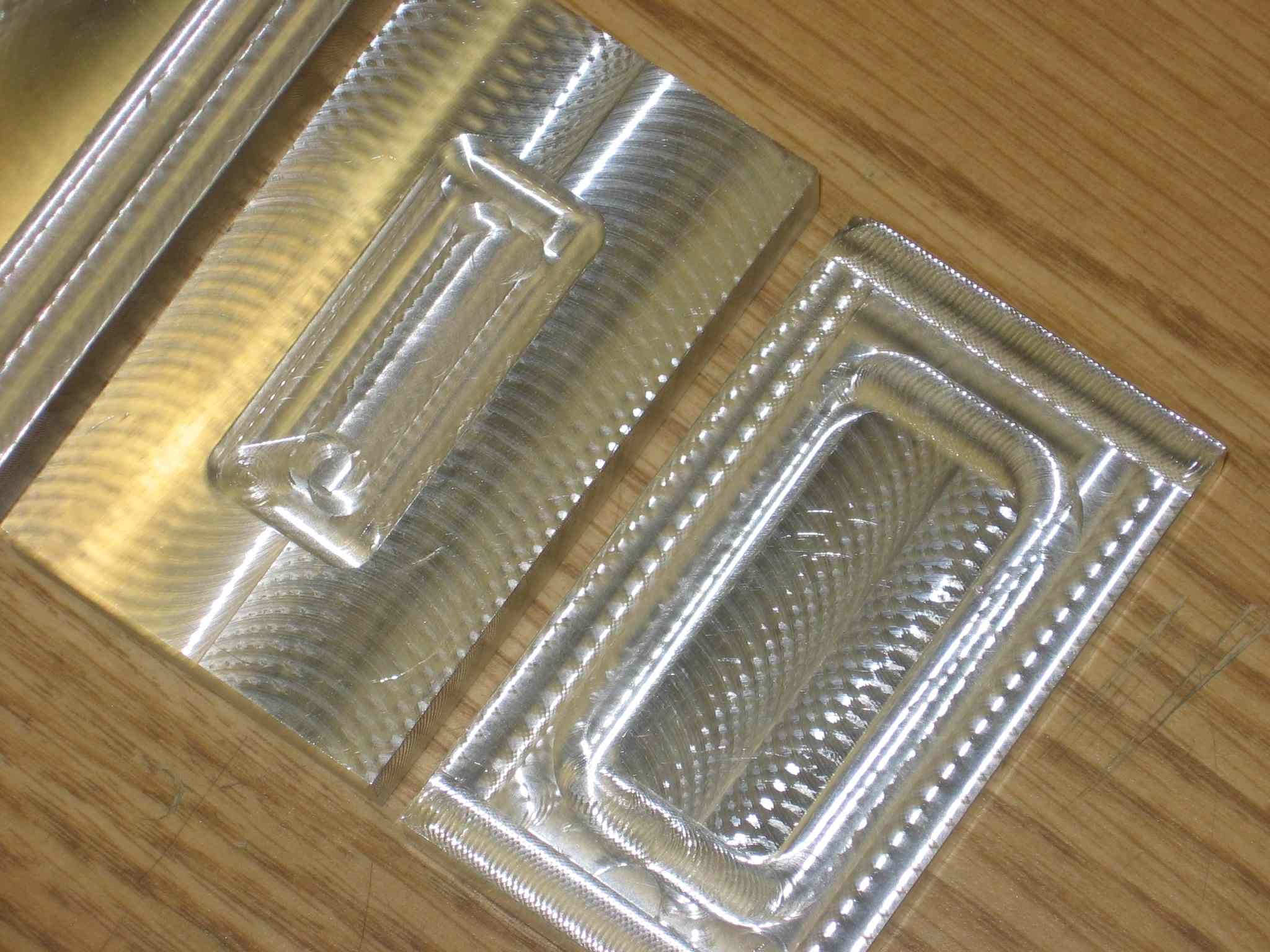
FIGURE 5 - POCKET (LEFT) PROFILE (RIGHT)
Face Milling
Face Milling uses a face mill to take large sweeps over the surface of the material each pass. Each pass is usually evenly spaced over the surface of the material as shown in the NCplot diagram in figure 6.
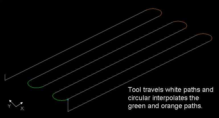
FIGURE 6 - FACE MILL NC PATH
The operation usually takes off a few thousands of an inch of material
on the top of the
block for squaring purposes. Also the face mill leaves a clean finish
that can
seen in figure 5 and 7. Figure 5 notice the wide passes uses a 2
carbide
tip
face mill. Figure 7 uses small passes to achieve the same result
but
uses a flat 4 flute end mill.
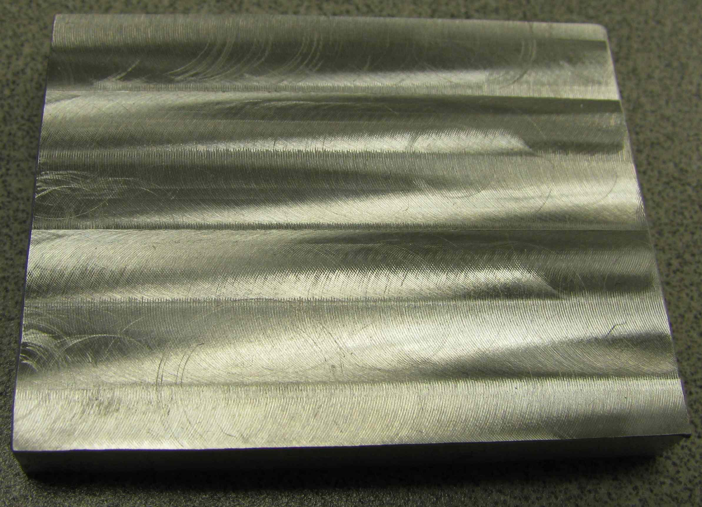
FIGURE 7 - FLAT 4 FLUTE FACE MILL