This article explains how I set up a contact probe to the parallel port of my EMC computer.
I wired up my computers +5V and 5V ground, from the power connector, to a 9 pin sub-D connector on the back of the computer for easy access. I also ran +12V and 12V ground to the sub-D for possible future use.
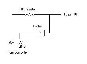
From there +5V goes to a 10,000 Ohm resistor and on to pin 10 of the parallel port. A parallel/branch wire is run to one side of the probe's contacts from between the 10K resistor and parallel port pin 10. The other side of the probe's contacts is connected to the computer's 5v ground.
I used a parallel port break out board from Camtronics. This board breaks out all of the pins from the port for motor connections, and also has 10K resistor packs for home/limit switches, probes, etc.
Now that the probe is wired up, there are a couple of values within the emc.ini file that have to be set in order for EMC to recognize and use the probe.
Within the emc.ini file, scroll down to the Trajectory Planner Section
[TRAJ]
PROBE INDEX = 3 (specifies pin 10 on parallel port)
PROBE POLARITY = 1 (matches the wiring scheme)
With the parameters in the emc.ini file set, we are ready to try out the Probe.tcl script and test the probe. You can start up this script from tkemc using the menu named scripts and the probe line.
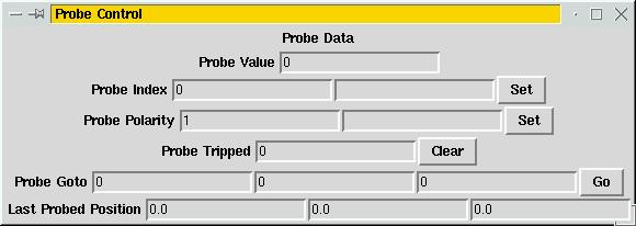
You should follow the steps listed below in order.
- Look at the probe index and see that it reads 3
- Look at the probe polarity and see that it reads 1
- If the Probe Tripped value is 1, press the Clear button to reset it to 0.
- The 3 text boxes, on the Probe Goto line, are for entering move values for X, Y, and Z, respectively.
- Put a move value in X of 1 inch and press the Go button.
- While the machine is moving, manually trip the probe.
If the machine stops and the Probe Tripped value is 1, you have successfully hooked up a contact probe.
This page is maintained by Allen
Last modified: Thursday Sep 13 2001